See.
Read the part, understand its surfaces, and turn raw CAD into geometric intent.
Robotics software engineer Available worldwide
From CAD geometry and motion planning to embedded control and real hardware. I build the entire path between intent and motion.
00 The premise
I work where disciplines collide: geometry becomes trajectories, trajectories become packets, and packets become physical movement.
The result is software that understands the machine above it—and the hardware below it.
01 One continuous system
Read the part, understand its surfaces, and turn raw CAD into geometric intent.
Generate a path, solve the arm, and prove reachability and clearance before the first joint moves.
Carry the trajectory through ROS2, CAN and motor control until mathematics becomes motion.
Measure what the real machine does, close the loop, and let evidence—not assumption decide what ships.
02 Selected work
Projects that cross simulation, software architecture and physical hardware—because a robot is not finished when the code compiles.
Pull a joint, attach a different one, and the robot discovers its new body. Distributed modules communicate over CAN while ROS2 and MoveIt2 rebuild the kinematic description at runtime.
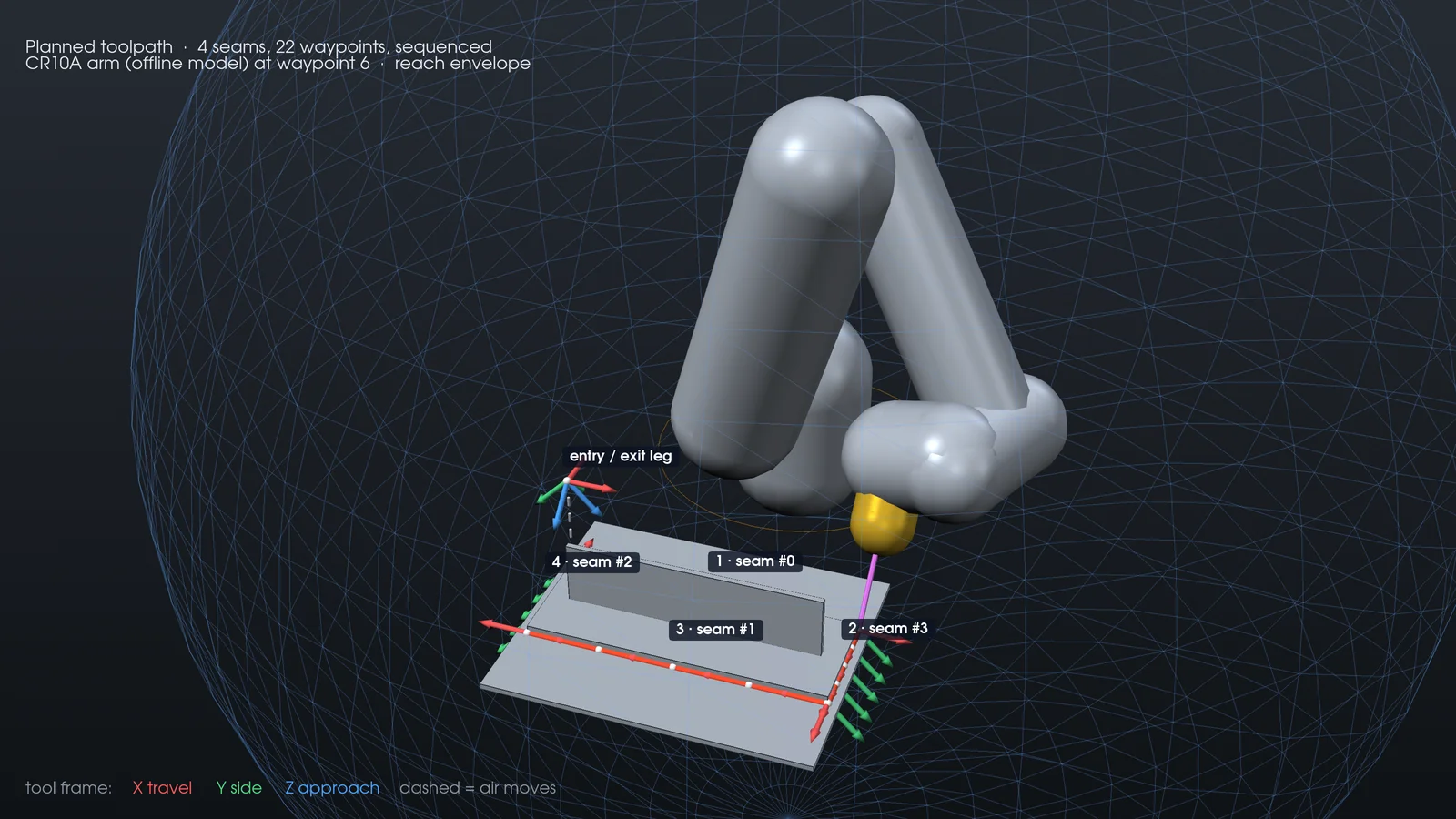
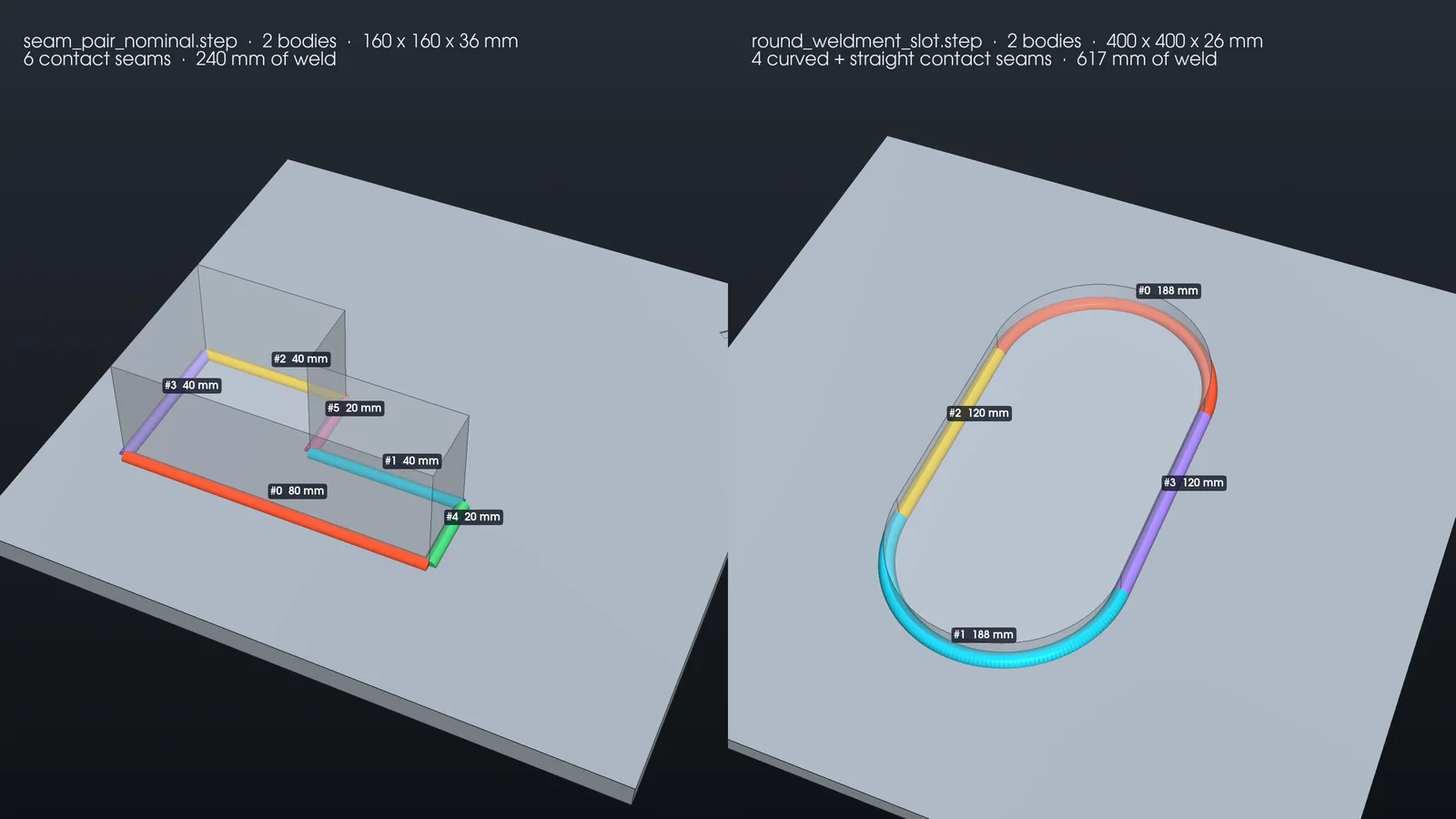
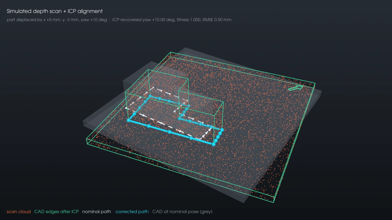
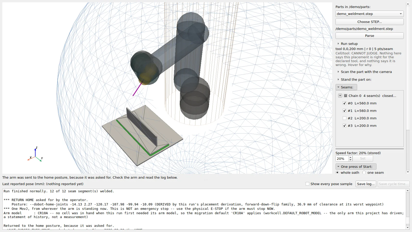
Give it a STEP file and it finds the weld seams, plans an oriented, sequenced toolpath and drives a Dobot CR10A over the controller’s own TCP/IP protocol. Seams are ordered by an exact Held–Karp search that weighs travel against wrist winding, every step is rule-based and explainable, and eight pre-flight checks can refuse a run before the first motion command. Lining the path up with the part from a depth scan (ICP) works in simulation; the wrist camera is now on the arm.
TÜBİTAK 1707: the system is now at the application stage as the core of an order-based industrial R&D project.
Field log
Connected, enabled and ran the full path on the real arm. One stop, from the controller’s own singularity alarm.
The wrist ran out of travel at waypoint 27. That failure became the wrist-budget check.
The first full path flown under every check: 8 seams, with a pen standing in for the torch.
Lens calibration of the industrial camera: 0.135 px RMS over 44 views.
The planner moved to a CR5A and wrote on paper. The camera went onto the wrist and found the sheet untaught.
All site runs were motion-only: no torch mounted, no arc struck.
Pre-flight checks
Hardware Dobot CR10A · Dobot CR5A · wrist-mounted industrial camera
Stack Python · CadQuery / OpenCASCADE · Open3D · PyVista · PyQt5
Pen test · Oct 2026 · Dobot CR5A
About 90% of the planner carried over to a smaller arm unchanged. We hand-guided it to the four corners of an A4 sheet and nothing else; every stroke of the lettering came from the planner, a pen standing in for the torch.
Meanwhile the camera went onto the wrist. In raw frames it already finds the sheet without its corners being taught. Next the two meet: the camera finds the sheet, the arm writes. On a shop floor that sentence reads: put the part down, and the robot finds it.
Why this is R&D
Drift more than about 0.5 mm off the seam and the arc starts missing one edge of the joint. A cobot returns to the same spot within ±0.03 mm, but going where it is told is a different number, and heat and the hose’s pull spend the rest. Warm the arm up and load the torch:
Estimates from catalogue figures and published measurements on comparable arms: a 1 m aluminium arm grows about 0.023 mm per °C, and a similar cobot gives 57–96 N/mm at the tip. Measuring them on our own arm comes first.
The plan
Heat drifts over hours, flex changes from one second to the next, so no single sensor catches both. Five loops, five speeds:
Learned the hard way On 21 Aug a tool frame left on the teach pendant moved every target by 440.9 mm, and any check reading that same setting saw nothing wrong. So each loop leans on a measurement that does not share the error it corrects.
A self-balancing platform built from the driver up: sensor fusion, six-step commutation and a deterministic PID loop.
LLM orchestration with deterministic engineering tools, source-backed claims and mandatory human approval before release.
03 Full vertical slice
I like the problems that live at the seams between disciplines—the ones nobody quite owns.
Turn shape and point clouds into something a robot can reason about.
Decide where the tool goes, whether the arm can reach, and how it gets there.
Carry intent into deterministic loops, buses and motor phases.
Build traceable software around the machine without asking AI to invent the physics.
04 Experience
Contract · Remote & on-site
CAD-to-robot weld path generation for a real collaborative arm: flown end to end on a Dobot CR10A, ported to a CR5A, and now at the TÜBİTAK 1707 application stage. Also a retrieval-grounded engineering feasibility platform.
BYRSAN Makina · Istanbul
PLC/HMI control, DIN-compliant structural engineering, and the company's digital infrastructure from site to quote-management system.
Tezmaksan Makina · Istanbul
FANUC robot programming and cell validation on the production floor, alongside industrial IoT dashboards with .NET Core.
Yıldız Technical University · Pamukkale University
M.Sc. thesis on autonomous modular robotics. Academic work spans controls, HIL test design and rigorous V-model verification.
Software engineer · product builder Open to projects
Beyond robotics I build complete products: mobile apps, web platforms, AI tools and games. From the first conversation with the people who'll use them to the release build.
01 Live demo
Kripros is open source and runs entirely in your browser: no sign-up, no server. Launch it inside the phone, or open it full screen.

Tip: tap “Örnek verilerle keşfet” to start with a few months of sample data. The interface is in Turkish.
A personal finance tracker for savings, spending and income, built with Expo and React Native. Budgets, recurring payments, goals, a calendar and charts drawn directly in SVG, and everything stays on the device.
02 Selected apps
Most of these live in private repositories, so what you see are real screens and clips captured from the running apps. Open any card for the full story.
A juicy retro-arcade block puzzle: five grid sizes, combo fever, power-ups and online leaderboards.
Meeting notes that write themselves while people are still talking: live Turkish transcription and topic notes.
One control layer for mixed-brand industrial cells: digital twins, a node-graph scenario designer and a single safety gate for every motion command.
Drives Claude Code, Codex and Antigravity from one place: agents hand work to each other, every task gets its own git worktree, nothing merges without you.
A private notebook for the people in your life: who to reach out to today, birthdays, notes and reminders, with end-to-end encrypted sync.
Follows every made-to-order furniture item from the maker to the customer’s door, encrypted in the browser with no server at all.
Savings, spending and income on the device: budgets, recurring payments, goals and hand-drawn SVG charts.
Upload a PDF or Word file, get a Turkish summary and chat with it; every answer cites its page.
Proposals for an industrial machinery maker: line items and terms in, a print-ready A4 quote out, with AI-drafted first versions.
An offline RAG assistant for CAN bus and firmware questions: it answers from your documents and cites them, or says it doesn’t know.
Dues and collections for apartment complexes, designed from the first line for volunteer managers over 65.
A family New Year tournament, scored live: five players, nine real-life games over three days and an AI quiz finale.
MathWorks Hackathon 2026: a phone in your pocket recognises what you’re doing and turns it into personal health metrics.
03 How I build
The same few rules keep showing up across these repositories: not as slogans on a slide, but as code.
If an app doesn’t need a server, it doesn’t get one. Kripros never leaves the phone, Mobilya Takip encrypts every record in the browser with per-user wrapped keys, and the CAN assistant answers with the network unplugged.
Amounts are stored in kuruş, never as floating point. Balances are computed from the ledger rather than stored, and a correction is a reversing entry, not a delete.
Mobilya Takip started from a discovery conversation in the shop, which is why it tracks missing parts rather than stock counts. Site Yönetim is shaped around 65+ volunteer managers: large type, plain Turkish, no jargon.
Models draft, summarise and suggest; they don’t get the keys. EOK’s AI has no handle on a single device, Konsey merges nothing without approval, the CAN assistant cites its source or refuses, and Conleaf saves nothing from a voice note until you confirm.
04 Smaller builds
Single-purpose tools and learning projects. Two of them you can open right now.
Two PDFs side by side with a draggable divider, for reading and comparing. One HTML file; documents never leave the browser.
An ASP.NET Core MVC shop with categories, cart, coupons, checkout and orders.
Hand-written HTML, CSS and JavaScript: a canvas motion field, scroll-driven kinematics, no framework.
05 Start a conversation


